John Deere 318 Ignition Switch Wiring Diagram (2024)

1. [PDF] 316, 318 AND 420 ELECTRICAL SCHEMATIC—SINGLE PTO

  • The green wire connects to terminal “B” of key switch (S1), not to circuit breaker (F3) as does the red. “210” wire. NOTE: 3. The electrical schematic shows ...

2. JD 318 pto switch - Yesterday's Tractors Forums

  • Nov 8, 2022 · If you look at the wiring diagram, the terminals on the switch are identified. Note that the switch box actually includes two switches. One ...

  • I'm putting the correct pto switch in a 318. Originally there were 2 plugs on the back of the switch.The plug that had 3 blue wires in it is gone leaving a single blue wire and a double blue wire that goes to the electric clutch. My question is the single blue wire that goes to the timer...

3. john deere 318 with P218G Onan engine - Yesterday's Tractors Forums

4. John Deere 318 - TractorByNet - Tractor Forum

  • Oct 8, 2016 · ... wiring diagrams. Having to re-wire, or track down a problem? Oct 8, 2016 / John Deere 318. Thread Starter. #3. OP. S · SmileyGurl2o04. New ...

  • Not Sure what year john deere 318 I have but im in need of wiring diagram for it.... any tips or help would be great thank you

John Deere 318 - TractorByNet - Tractor Forum

5. Ignition Switch fits 108 112 116 316 318 420 GS25 with Keys

  • JOHN DEERE S910 and S930 front mount, 108, 112, 116 lawn tractors, 316, 318, 420 garden tractors, GS25, GS30, GS45, GS75, HD45, HD75, 111 series 120000 and ...

  •   Ignition Switch fits John Deere 108 112 116 316 318 420 GS25 with Keys Stens 430-110 Ignition Switch Description:   STARTER SWITCH JOHN DEERE/AM38227 Pack Size: 1   Replaces (OEM):   JOHN DEERE AM38227 ARIENS: 03602300 GRAVELY: 03602300   Fits Models:   JOHN DEERE S910 and S930 front mount, 108, 112, 116 lawn tractors, 316, 318, 420 garden tractors, GS25, GS30, GS45, GS75, HD45, HD75, 111 series 120000 and higher ARIENS 915001-915023 915301-915308 931037 931038 93130, 931302, 931303, 934023-934027, 934301, 936002-936026, 936301-936319, 988315-988321, 988811 and 992028   Specs:   Ignition Type:Magneto No. Of Positions:3 No. Of Terminals:6 Starter switch 9/16" mounting stem Made by Indak     AN / Rev AN  

Ignition Switch fits 108 112 116 316 318 420 GS25 with Keys

6. Does anyone have an ignition switch wiring diagram or know the colors?

  • Jan 6, 2008 · I am looking to find out what each wire is such as 12v+, ignition wire, etc... In the pics below are the wires coming from the switch I am ...

  • Bimmerforums is the preferred online BMW Forum and community for BMW owners. At Bimmerforums, you will find technical how-to information maintenance specifics audio advice wheel and tire combinations and model specific details not found anywhere else. Our professionals are here to help make sure you find the answers you need to your questions and our community is here to help other brainstorm ideas for the future.

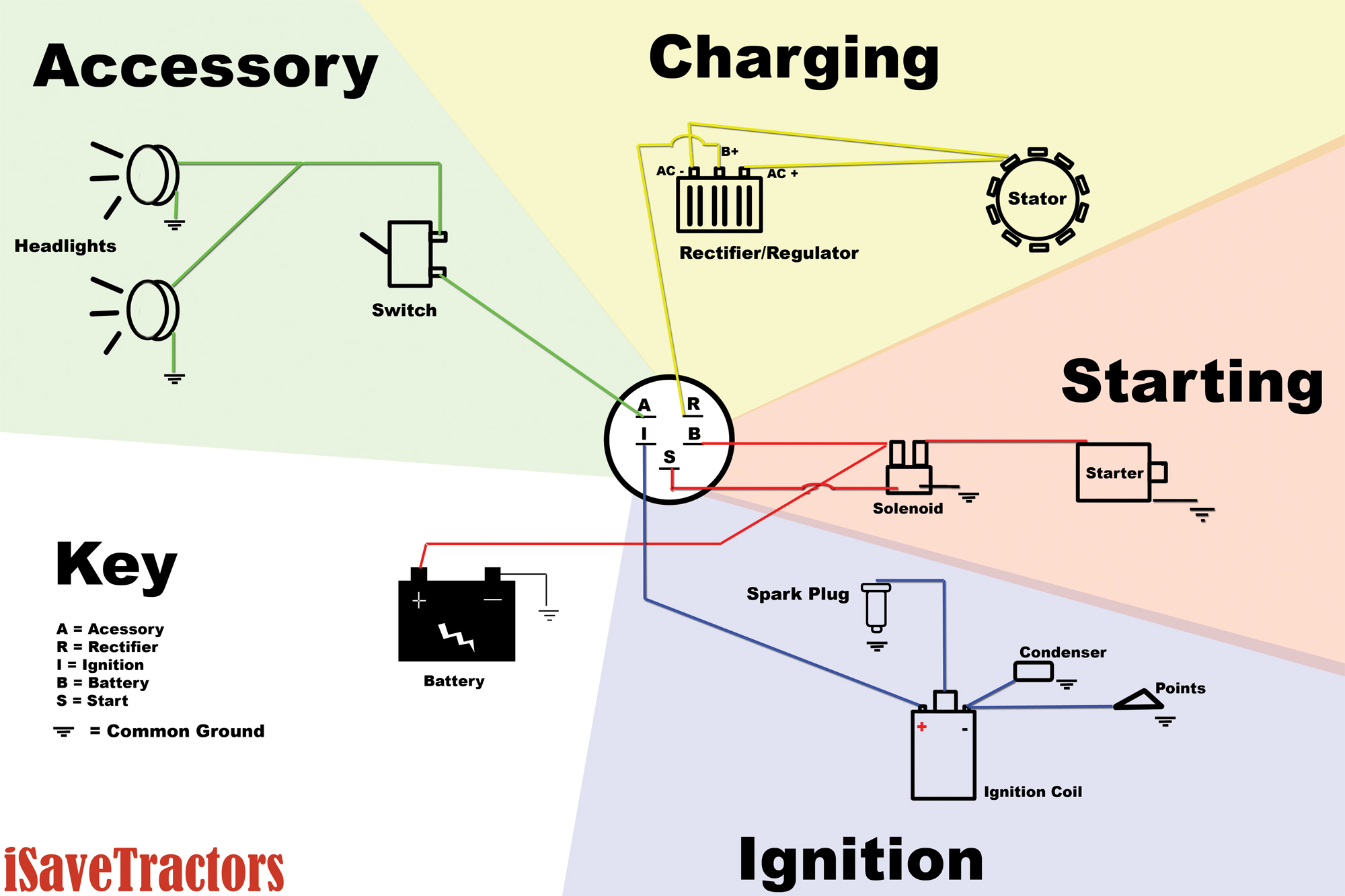
7. Basic Wiring Diagram for all Garden Tractors using a Stator and Battery ...

  • We did our best to keep this as simple and as easy to understand as possible. This applies to all old Cub Cadet, Ford, Jacobsen, John Deere, Wheel Horse, Case, ...

  • Here is a basic wiring diagram that applies to all Vintage and Antique Lawn and Garden Tractors using a Stator Charging System and a Battery Ignition System. We did our best to keep this as simple and as easy to understand as possible. This applies to all old Cub Cadet, Ford, Jacobsen, John Deere, Wheel Horse, Case, and Simplicity Garden Tractors. 

Basic Wiring Diagram for all Garden Tractors using a Stator and Battery ...

8. John Deere 318 Starter wiring issues - TractorByNet

  • Jun 12, 2013 · Seems like I am miising a wire and can not find it. I also bought a new solenoide and ignition switch today. NO luck.

  • I have a John Deere 318 with the Onan motor. The starter went out last year when I installed a new battery. The windings must have went to ground on the starter. Everytime I hooked the battery up it would pop becauce the started was grounded out. A year later last weekend I pulled the motor...

John Deere 318 Starter wiring issues - TractorByNet

9. Lawn Mower Parts | John Deere US

  • Find Parts. Search part numbers and John Deere parts diagrams to identify exactly what you need to keep your equipment running smoothly. Search Parts Catalog.

  • Order lawn mower parts including lawn mower blades, filters, and belts. View our John Deere parts catalog, maintenance and repair sheets, DIY videos, and more.

John Deere 318 Ignition Switch Wiring Diagram (2024)

FAQs

What color is the ignition switch wire? ›

Known as the IGN or ignition input wire, the yellow or red wire signals your car's ignition system to turn on. Without it, you might find yourself stranded on the side of the road with a car that won't start. The brown or yellow wire is the Starter (ST) wire.

Where does ignition wire go? ›

Attach the ignition wire to the IGN terminal.

What are the numbers on the ignition switch? ›

The ignition switch has four positions: LOCK (0), ACCESSORY (I), ON (II), and START (III). Use this position only to start the engine. The switch returns to the ON (II) position when you let go of the ignition switch.

What is the color code for the switch wires? ›

See Table below. The protective ground is green or green with yellow stripe. The neutral is white, the hot (live or active) single phase wires are black , and red in the case of a second active. Three-phase lines are red, black, and blue.

What is the color of the wire in which switches need to be connected? ›

Switching is another area where red wire is used. In a circuit, there might be multiple switches for one function (switching on a light or a fan, etc.) from different locations. A red wire is used for this purpose.

What happens if the ground wire becomes disconnected on the ignition switch? ›

If the ground wire between the magneto and the ignition switch becomes disconnected, the most noticeable result will be that the engine fails to start. The most obvious effect of a disconnected ground wire between the ignition switch and magneto is a failed engine start or loss of power.

What is the ignition switch connected to? ›

The ignition switch performs a primary function in that it connects the circuit that provides voltage to your starter motor, allowing the engine to crank over and the engine to eventually start. In older vehicles it's part of the key barrel, and you activate the ignition switch by turning the key.

What does the ignition switch supply power to first? ›

Once the ignition switch is prompted by key or the push of a button, it activates the voltage from the battery to the ignition coil to produce the engine spark. The engine spark from the coil or coils is directed to the spark plugs to ignite the fuel to make the vehicle run.

Which wire should an ignition acc connect to? ›

Generally, the black wire connects to the negative, the yellow wire connects to the turn signal lights, and the red wire connects to the ACC (Accessory) position. To locate the ACC position, you'll need to access the fuse box.

What does R1 and R2 mean on an ignition switch? ›

Terminals "R1" and "R2" are used when preheating the engine during cold weather starts." R1" receives current when the key is held in theHEATposition. " R2" gets current during cranking.

What color wire is power switch? ›

It is sometimes black or red. Also known as a hot, live or switch leg wire.

What color is the hot wire on a light switch? ›

Here's a rundown of electrical wires: The black wire is the "hot" wire, it carries the electricity from the breaker panel into the switch or light source. The white wire is the "neutral" wire, it takes any unused electricity and current and sends it back to the breaker panel.

What is the pink wire on the ignition switch? ›

The pink wire is as an ignition input sensor used to control the operation of the main engine relays contained within the Haltech Fuse Box. It needs to be connected so that it sees 12V only when the ignition switch is on and during cranking.

How do you check for a bad ignition wire? ›

Remove a spark plug wire from any plug. Attach a spark tester to the wire and to an engine ground. Crank the engine and check for a good spark at the spark tester gap. A good spark will be blue-white and will be plainly visible in daylight.

References

Top Articles
Latest Posts
Article information

Author: Neely Ledner

Last Updated:

Views: 6306

Rating: 4.1 / 5 (42 voted)

Reviews: 81% of readers found this page helpful

Author information

Name: Neely Ledner

Birthday: 1998-06-09

Address: 443 Barrows Terrace, New Jodyberg, CO 57462-5329

Phone: +2433516856029

Job: Central Legal Facilitator

Hobby: Backpacking, Jogging, Magic, Driving, Macrame, Embroidery, Foraging

Introduction: My name is Neely Ledner, I am a bright, determined, beautiful, adventurous, adventurous, spotless, calm person who loves writing and wants to share my knowledge and understanding with you.